Part 2: Implementing a PI Controller with an Arduino
Table of Contents
Introduction
This lesson will walk through using an Arduino to control local brightness in a small volume using a light-emitting diode (LED) as an "actuator" and a photocell as a sensor.
Learning Objectives
Students will be able to
- identify a light emitting diode (LED), understand its function, and connect it into a circuit
- use pulse-width modulation (PWM) to mimic analog output for actuation
- identify a photocell, understand its function, and connect it into a circuit
- use a voltage divider to sense change in resistance of a photocell
- implement and tune a proportional-integral controller on a microcontroller
- write a program to integrate all of this information
Introduction to the Arduino IDE and Setup (10 minutes)
Interactive demo of main IDE features:
- Code editor
- Verify sketch (blank)
- Board selection
- Port selection
- Upload sketch (blank)
- Serial monitor/plotter
For more in-depth descriptions of the IDE, see the official guide
The Kit Components
Check the kit that you received and make sure that it has below components. Our final circuit requires:
- Arduino Uno Micro Controller with USB cable
- Small Breadboard
- an LED
- a photocell (photoresistor, light-dependent resistor)
- 4-8 jumper wires
- a 4.7kΩ resistor (yellow, purple, red, [gold])
- a 330Ω resistor (orange, orange, brown, [gold])
If you are missing any component or you find out that they are not working, let us know.
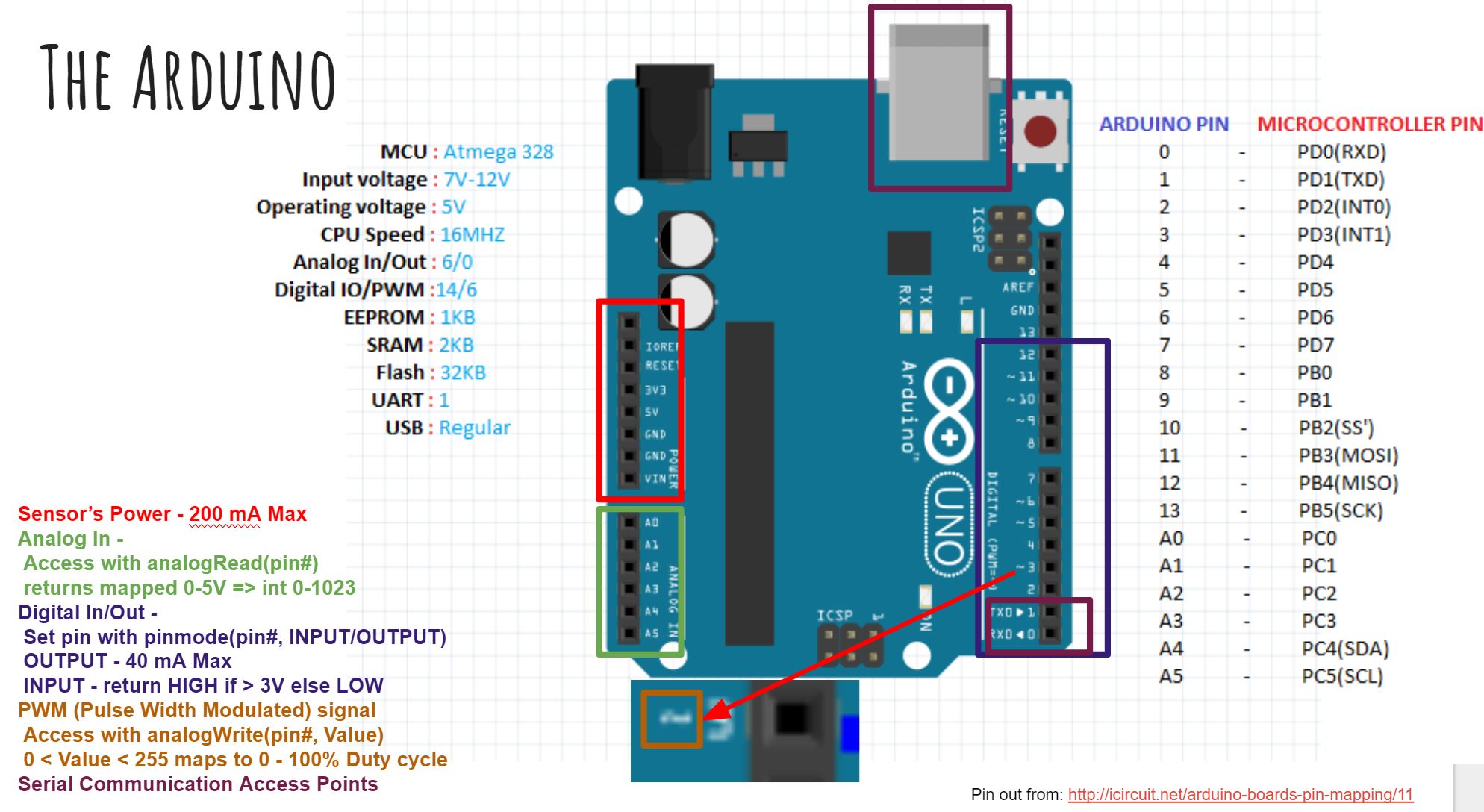
Arduino Uno Microcontroller
The basics of the Arduino microcontroller were discussed in the part 1 lecture. The Arduino requires a power source to work and the USB cable offers a way to both supply power and upload code into its memory simultaneously. For an actual application, standard practice is to upload and test your code with the USB first and then use a dedicated power supply to power the Arduino via power jack (large round socket in black).
Basic circuit modules
Analog circuits are circuits dealing with signals free to vary from zero to full power supply voltage. This stands in contrast to digital circuits, which almost exclusively employ “all or nothing” signals: voltages restricted to values of zero and full supply voltage, with no valid state in between those extreme limits.
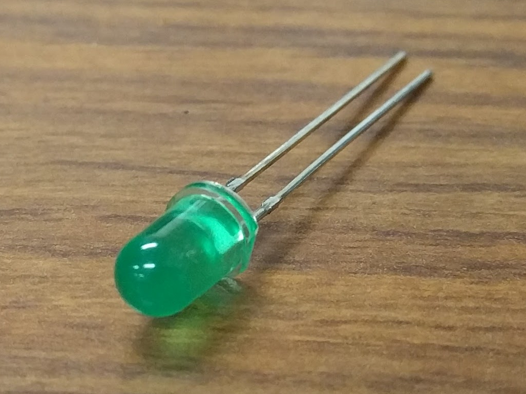
Light Emitting Diodes (LED)
Light emitting diodes (LEDs) are semiconductor devices that emit light when voltage is applied across them. LEDs typically have a fixed voltage drop of around 2V (depends on the LED), which is the voltage required to cause it to illuminate. The brightness can then be controlled directly by varying the current going through the device. In most applications (e.g. indicators), a current-limiting resistor is connected in series with the LED to provide a fixed brightness for a given control voltage.
In our application, we will use a fixed current-limiting resistor of 330Ω and a 5V control voltage, but we will use a technique called pulsewidth modulation (PWM) to effectively vary the current passing through the circuit.
PWM works by rapidly toggling a digital output between its high (e.g. 5V) and low (e.g. 0V) values, with varying durations of on and off time. The ratio of the on time to the total period of the PWM signal is referred to as duty cycle, and is expressed as a percentage. The logic behind this is: if you were to integrate the voltage over one period of the PWM signal, the effective voltage would be the duty cycle times the "on" voltage level. If the switching is fast enough, many sensors (including our own eyes) will not be able to detect that the actuator (e.g. an LED) is actually turning on and off, but instead it will detect an intermediate output roughly corresponding to the equivalent voltage level. For mechanical systems, such as DC motors, the mechanical dynamics are often slow enough with respect to the PWM signal that their output will actually smoothly vary.
The Arduino Uno allows us to output a PWM signal on several of its pins. This is done by setting the pin as an output, and using the analogWrite function. This function accepts an unsigned (positive) 8-bit integer value ((2^8)-1) between 0 (pin fully off, 0% duty cycle) and 255 (pin fully on, 100% duty cycle).
Exercise 1: Vary the LED Brightness (15 minutes)
- Start by connecting the 5V pin output and GND pin of the Arduino to the red and blue "power rails" of your breadboard. This is good practice while using a breadboard.
- LEDs are directional components, so ensure that the cathode is connected to ground (see diagram below). Connect the 330Ω resistor to the other lead, and connect the resistor to pin 5 of the Arduino using a jumper wire.
- Check your circuit against the diagram below. Leave the circuit constructed throughout the session.
- With this circuit hooked up, you can test its operation. Add to the code
below to repeatedly ramp up the brightness of LED from off to fully on over
a few seconds each time. You'll need the analogWrite function as well as
the delay function. HINT: you can also use a 'for' loop to vary the input to the analogWrite function smoothly.
Note that the pin number for the LED has been specified
via a preprocessor macro.
This is a special statement that literally substitutes each occurence of
LED_PINwith the value 5, saving some of the limited memory in the microcontroller.
#define LED_PIN 5

void setup() {
    pinMode(LED_PIN, OUTPUT);
}

void loop() {
    // add code here
}
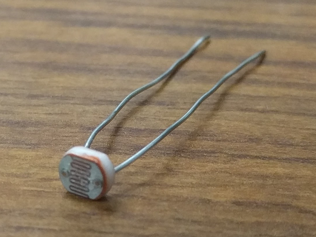
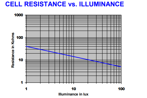
Photocells
Photocells are passive circuit elements which change their resistance in response to a change in brightness. Their resistance decreases when the ambient environment becomes brighter. The datasheet for our photocell provides an approximate relationship between resistance and the illuminance hitting the sensor:
An Arduino can sense voltages from 0V to 5V through the analog input pins, but it has no direct way of sensing resistance. Since our sensor operates by changing resistance, we need to convert this to a change in voltage. This is achieved through a voltage divider circuit.
In this circuit, we supply 5V from the Arduino as \(V_{\text{in}}\) and measure \(V_{\text{out}}\) with one of the Arduino's analog input pins (pin A0). The output voltage for this voltage divider is given by
When the brightness increases, the photocell resistance \(R_s\) decreases, so the output voltage \(V_{\text{out}}\) increases. In our example, we will simply convert the value read in by analogRead to a voltage and use it as a substitute for "brightness". The input comes in the form of a 10-bit unsigned integer, so it has the range of 0 to 1023 (\(2^{10} - 1 = 1023\)), corresponding to 0V up to 5V, respectively. If we read a value of \(x\), we can map this value to a voltage as follows:
Exercise 2: Read from the Photocell (15 minutes)
- Leave the 5V and GND connections from the LED example intact, then place one of the photocell leads on the 5V rail. A photocell is essentially a resistor, so its orientation in the circuit doesn't matter.
- Bend the photocell's leads to 90° so that it faces the LED.
- Connect the other lead of the photocell to the 4.7kΩ resistor which goes to GND.
- Use a jumper wire to connect the junction between the photocell and the 4.7kΩ resistor to the Arduino's A0 pin.
- Check your circuit against the diagram above.
- Create a new sketch using the Arduino IDE and replace it with the following code. Write your own statements to read in the input value (10-bit unsigned int), cast (convert) that reading to a floating point value, convert the brightness value into voltage using the formula above then print the voltage to the serial port. You will need to make use of the analogRead and Serial.println functions.
#define SENSOR_PIN A0

void setup() {
    Serial.begin(9600);
    pinMode(SENSOR_PIN, INPUT);
}

void loop() {
    // add code here

    delay(50);
}
- Once the code is uploaded and running, use the Arduino IDE's serial monitor or serial plotter to view the values being read. What happens to the voltage if you cast shadows over the circuit?
- Allow the voltage to settle to a steady value. Use the serial monitor to record the numerical value. This voltage corresponds to the ambient brightness in the room.
Control System
Now we'll put the LED and photocell together in order to obtain a desired brightness level. Here is a block diagram of the control system we will implement to achieve this:
In this controller example, we will use voltage as a representation of brightness. Because of the voltage divider configuration, the voltage read by the Arduino's input pin will vary proportionally to the brightness sensed by the photocell.
The measured voltage is compared to a voltage representing the desired brightness, resulting in some error. This error is then fed into a controller, which transforms the error into a PWM signal to change the LED brightness. For example, if the measured brightness is lower than desired, the error will be positive, and the controller coefficients will produce a positive PWM signal to drive the LED to become brighter. This has the effect of increasing the measured voltage, hence decreasing the error. This kind of controller configuration is called a regulator, and its job is to achieve and maintain zero error between the measured output and the desired output.
Circuit Construction
Now let's put together the hardware of our control system. The photocell will be the sensor and the led will be the actuator that we control. Our goal is to control the local brightness of small volume surrounding our sensor.
The circuit consists of a light emitting diode (LED) circuit, driven by one of the Arduino's digital I/O pins capable of producing a pulsewidth modulation (PWM) signal. This will allow the LED’s brightness to change. A photocell facing the LED senses the ambient lighting. The objective of the circuit is to demonstrate an automatic feedback control system that drives the LED to a desired brightness level near the sensor. You will be able to cast shadows on the photocell and watch as the LED brightness increases to compensate for the dimmed lighting.
Both components (the LED and the photocell) should be connected from the previous two sections. The most important part of the control circuit construction (aside from making the correct electrical connections) is that the LED and photocell are close to and facing one another. This will ensure that the LED is able to influence the reading of the sensor as much as possible.
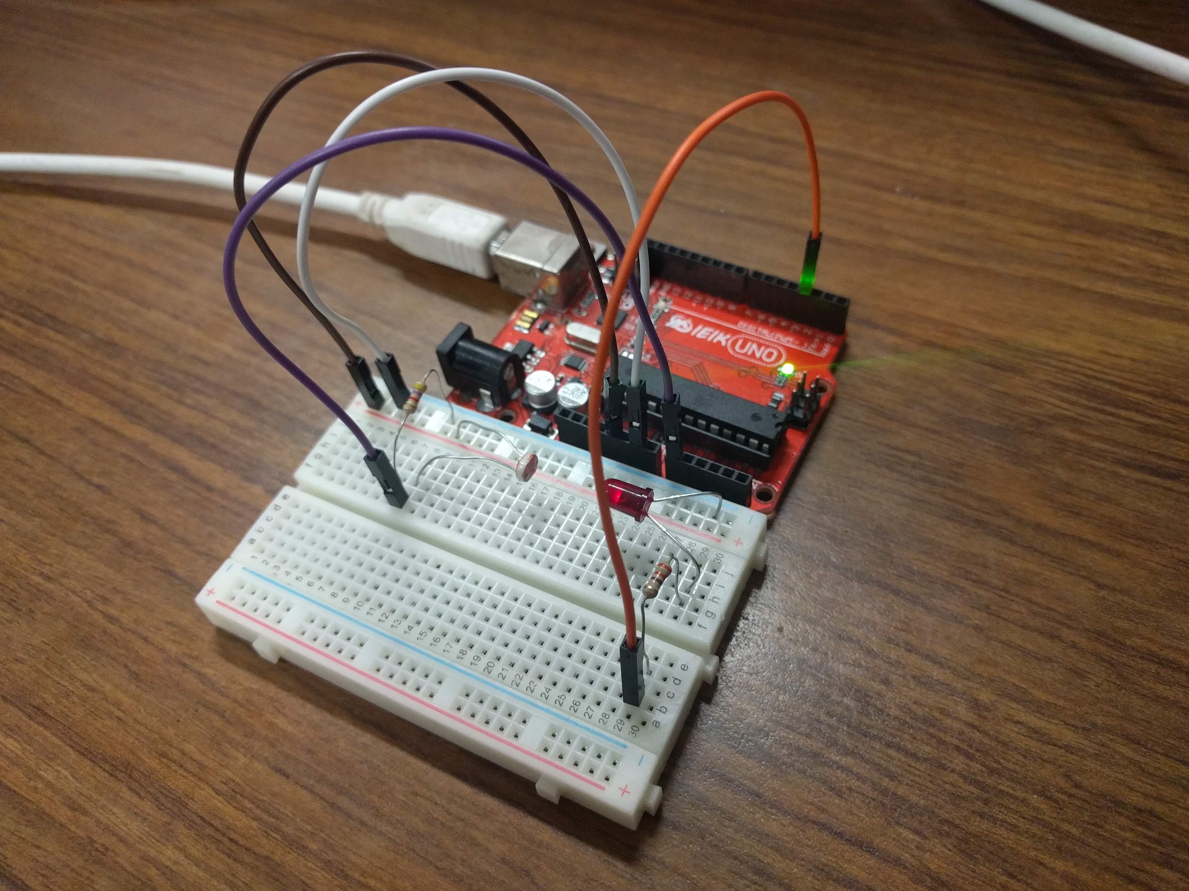
Once constructed, the circuit should look like the image below:
Implementing the Controller
Excercise 3: Finding a Setpoint (5 minutes)
- Start with the photocell reading code you finished.
- Add to that sketch the code for setting up the LED (refer to the first code
listing for help), then use the analogWrite function inside
setupto turn the LED on at 30% duty cycle. - Run the sketch and observe the voltage output by the photocell circuit. Write this value down as this will be the desired brightness level we will seek to achieve with an automatic control system.
Exercise 4: Implement a Proportional Controller (15 minutes)
- Create a new sketch based on the code below. You will need to replace the
value of
rwith the setpoint you found in the previous exercise, and you will have to implement the controller equations insideloopto findy,e, andu. For now, leave \(K_{p} = 0\) and use \(u(t) = K_p e(t)\).
#define SENSOR_PIN A0
#define LED_PIN 5

// desired voltage (change this to the value you found)
float r = 2;

// proportional controller coefficient (change to tune controller)
float Kp = 0;

// Initialize Global variables
// reading from the photocell
float y = 0;
// error between the desired output and the reading
float e = 0;
// output to send to the LED
float u = 0;

void setup() {
    Serial.begin(9600);
    pinMode(SENSOR_PIN, INPUT);
    pinMode(LED_PIN, OUTPUT);
}

void loop() {


    // store your measured voltage in this variable
    y =

    // compute the error between the measurement and the desired value
    e =

    // compute the control effort by multiplying the error by Kp
    u =

    // make sure the output value is bounded to 0 to 255 using the bound function defined below

    u = bound(u, 0, 255);
    analogWrite(LED_PIN, u); // then write it to the LED pin to change control voltage to LED

    // plot the measurement
    Serial.print(y);
    Serial.print('\t');
    // plot the desired output
    Serial.print(r);
    Serial.print('\t');
    // plot the error
    Serial.println(e);

    delay(50);
}

// Bound the input value between x_min and x_max.
float bound(float x, float x_min, float x_max) {
    if (x < x_min) { x = x_min; }
    if (x > x_max) { x = x_max; }
    return x;
}
- Once the code is uploaded and running, open up the serial plotter. The series of Serial.print statements in the code plots the measurement signal \(y(t)\), the reference signal \(r(t)\) (constant), and the error signal \(e(t)\). Perturb the brightness reading of the photocell by casting shadows on it and figure out which line is which.
- Let the signals become steady, then use the error measurement to make an estimate of what \(K_{p}\) should be to drive the error to zero. Recall that the reference value was found by producing a PWM signal at 30% duty cycle, so the term \(u(t) = K_{p}e(t)\) should be approximately \(0.3 \times 255 = 76.5\). If \(u(t)\) should be 76.5, what should \(K_{p}\) be? This initial guess will likely produce a proportional constant that is too high and causes instability. Divide it by 2 to start and try different values. Note the steady state error.
- Now try casting shadows over the circuit. Looking at the LED itself, does it seem to compensate when less light from the ambient environment hits the photocell? What do you observe when looking at the error signal in the serial plotter?
Exercise 5: Adding Integral Control (15 minutes)
As you probably have noticed, proportional controllers may suffer from non-zero steady state error. That is, there is a consistent mismatch between the desired and measured outputs, but the controller does not compensate for it exactly. To fix this problem, we can implement an integral control component, which adds to the controller output a multiple of the total integral of the error over all time. If a small but steady error is present, the integral of this error over time will become large, and the integral component of the controller will increase the total controller output to drive the error down to zero.
- Starting with the code you wrote to implement the proportional controller, introduce a global variable \(K_{i}\) and set it to an order of magnitude smaller than \(K_{p}\).
- Introduce a variable to keep track of the total accumulation of error. Each time the error is calculated, add it to the current value of the error accumulator variable.
- Modify the line that computes the PWM control value to use the full control equation:
- Upload the sketch and open the serial plotter. What happens if you cast shadows on the circuit now?
- Play around with \(K_p\) and \(K_i\). What does increasing or decreasing these coefficients do? Compare your observations to some of the information on Wikipedia's extensive article on PID control