5. Clock Pendulum with Air Drag and Joint Friction

This notebook builds on the previous one by introducing both a nonlinear pendulum and a nonlinear damping effect through Coulomb friction. Students will be able to work with both a linear and nonlinear version of the same system (a clock pendulum) in order to compare the free response in both cases.

After the completion of this assignment students will be able to:

  • compute the free response of a non-linear compound pendulum
  • estimate the period of oscillation of a nonlinear system
  • compute the free response of a non-linear compound pendulum with Coulomb damping
  • compare the non-linear behavior to the linear behavior
  • identify the function that governs the decay envelope for Coulomb damping

A common source of damping and energy dissipation is friction, which is a specific type of damping. With viscous damping, we had a torque that was linearly proportional to the angular velocity:
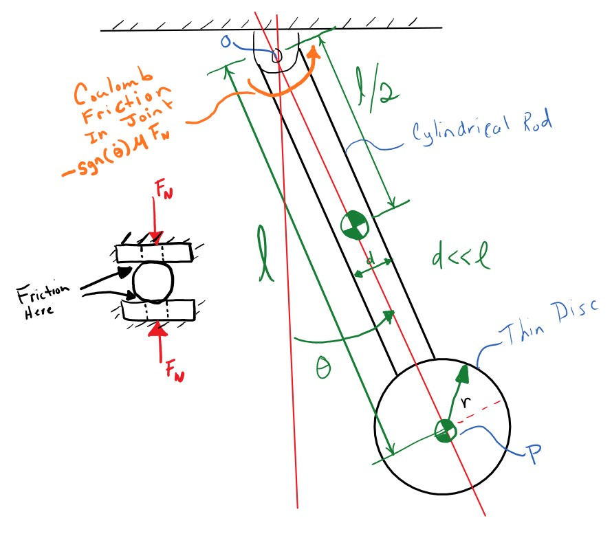
$$T_f = c l^2 \dot{\theta}$$

This simple source of energy dissipation is a reasonable mathematical model for many phenomena, but it isn't often a good model for dry friction between to hard materials. One very useful model of friction is Coulomb friction. Coulomb friction behaves more like:

$$T_f = \begin{cases} -\frac{2}{3}\mu R F_N & \dot{\theta} > 0 \\ 0 & \dot{\theta} = 0 \\ \frac{2}{3}\mu R F_N & \dot{\theta} < 0 \end{cases}$$

where $\mu$ is a coefficient of sliding friction, $R$ is the outer radius of the joint contact (assuming disc/disc contact, see http://www.iitg.ernet.in/kd/Lecture%20Notes/ME101-Lecture15-KD_DivI.pdf for an explanation), and $F_N$ is the normal force in the pivot joint. Here the damping torque is constant, always impeding the motion of the system.

This can also be more simply written using the signum function:

$$ T_f = -\frac{2}{3}\mu R F_n \text{sgn}\left( \dot{\theta} \right)$$

To start import some of the common packages we will need:

In [1]:
import numpy as np
import matplotlib.pyplot as plt

%matplotlib inline

Linear vs Nonlinear

resonance has both a version of the clock pendulum with the viscous damping (a model of air drag) and Coulomb friction (a model of joint friction). The first is a linear system due to the torque being linear in the angular velocity and the second is a nonlinear system because the torque is nonlinear with respect to the velocity. Import them both:

In [2]:
from resonance.nonlinear_systems import ClockPendulumSystem as NonLinPendulum
from resonance.linear_systems import ClockPendulumSystem as LinPendulum
In [3]:
non_lin_sys = NonLinPendulum()
In [4]:
help(NonLinPendulum)
Help on class ClockPendulumSystem in module resonance.nonlinear_systems:

class ClockPendulumSystem(SingleDoFNonLinearSystem)
 |  This system represents dynamics of a compound pendulum representing a
 |  clock pendulum. It is made up of a thin long cylindrical rod with a thin
 |  disc bob on the end. Gravity acts on the pendulum to bring it to an
 |  equilibrium state and there is option Coulomb friction in the joint. It is
 |  described by:
 |  
 |  Attributes
 |  ==========
 |  constants
 |      bob_mass, m_b [kg]
 |          The mass of the bob (a thin disc) on the end of the pendulum.
 |      bob_radius, r [m]
 |          The radius of the bob (a thin disc) on the end of the pendulum.
 |      rod_mass, m_r [kg]
 |          The mass of the then cylindrical rod.
 |      rod_length, l [m]
 |          The length of the rod which connects the pivot joint to the center
 |          of the bob.
 |      coeff_of_friction, mu [unitless]
 |          The Coulomb coefficient of friction between the materials of the
 |          pivot joint.
 |      joint_friction_radius, R [m]
 |          The radius of the contact disc at the pivot joint. The joint is
 |          assumed to be two flat discs pressed together.
 |      joint_clamp_force, F_N [N]
 |          The clamping force pressing the two flat discs together at the
 |          pivot joint.
 |      acc_due_to_gravity, g [m/s**2]
 |          The acceleration due to gravity.
 |  coordinates
 |      angle, theta [rad]
 |          The angle of the pendulum relative to the direction of gravity.
 |          When theta is zero the pendulum is hanging down in it's equilibrium
 |          state.
 |  speeds
 |      angle_vel, theta_dot [rad / s]
 |          The angular velocity of the pendulum about the revolute joint axis.
 |  
 |  Method resolution order:
 |      ClockPendulumSystem
 |      SingleDoFNonLinearSystem
 |      MultiDoFNonLinearSystem
 |      resonance.system.System
 |      builtins.object
 |  
 |  Methods defined here:
 |  
 |  __init__(self)
 |      Initialize self.  See help(type(self)) for accurate signature.
 |  
 |  ----------------------------------------------------------------------
 |  Methods inherited from MultiDoFNonLinearSystem:
 |  
 |  __str__(self)
 |      Return str(self).
 |  
 |  ----------------------------------------------------------------------
 |  Data descriptors inherited from MultiDoFNonLinearSystem:
 |  
 |  diff_eq_func
 |      A function that returns the time derivatives of the coordinates and
 |      speeds, i.e. computes the right hand side of the explicit first order
 |      differential equations. This equation looks like the following for
 |      linear motion::
 |      
 |          dx
 |          -- = f(t, q1, ..., qn, u1, ..., un, p1, p2, ..., pO)
 |          dt
 |      
 |      where:
 |      
 |      - x: [q1, ..., qn, u1, ..., un], the "state vector"
 |      - t: a time value
 |      - q: the coordinates
 |      - u: the speeds
 |      - p: any number of constants, O is the number of constants
 |      
 |      Your function should be able to operate on 1d arrays as inputs, i.e.
 |      use numpy math functions in your function, e.g. ``numpy.sin`` instead
 |      of ``math.sin``. Besides the constants, coordinates, and speeds, there
 |      is a special variable ``time`` that you can use to give the current
 |      value of time inside your function.
 |      
 |      .. note:: The function has to return the derivatives of the states in
 |         the order of the ``state`` attribute.
 |      
 |      Example
 |      =======
 |      >>> sys = SingleDoFNonLinearSystem()
 |      >>> sys.constants['gravity'] = 9.8  # m/s**2
 |      >>> sys.constants['length'] = 1.0  # m
 |      >>> sys.constants['mass'] = 0.5  # kg
 |      >>> sys.constants['omega_b'] = 0.1  # rad/s
 |      >>> sys.coordinates['theta'] = 0.3  # rad
 |      >>> sys.speeds['omega'] = 0.0  # rad/s
 |      >>> sys.states  # note the order!
 |      {'theta': 0.3, 'omega': 0.0}
 |      >>> def rhs(theta, omega, gravity, length, mass, omega_b, time):
 |      ...     # Represents a linear model of a simple pendulum under
 |      ...     # sinusoidal torquing.
 |      ...     #  m * l**2 ω' + m * g * l * sin(θ) = sin(ω_b * t)
 |      ...     thetad = omega
 |      ...     omegad = (np.sin(omega_b * time) -
 |      ...               mass*gravity*length*np.sin(theta)) / mass / length**2
 |      ...     return thetad, omegad  # in order of sys.states
 |      >>> sys.diff_eq_func = rhs
 |  
 |  ----------------------------------------------------------------------
 |  Methods inherited from resonance.system.System:
 |  
 |  __repr__(self)
 |      Return repr(self).
 |  
 |  add_measurement(self, name, func)
 |      Creates a new measurement entry in the measurements attribute that
 |      uses the provided function to compute the measurement given a subset of
 |      the constants, coordinates, speeds, other measurements, and time.
 |      
 |      Parameters
 |      ==========
 |      name : string
 |          This must be a valid Python variable name and it should not clash
 |          with any names in the constants, coordinates, or speeds dictionary.
 |          This string can be different that the function name.
 |      func : function
 |          This function must only have existing constant, coordinate, speed,
 |          or measurement names, and/or the special name ``'time'`` in the
 |          function signature. These can be a subset of the available choices
 |          in constants, coordinates, speeds, measurements and any order in
 |          the signature is permitted. The function must be able to operate on
 |          both inputs that are a collection of floats or a collection of
 |          equal length 1D NumPy arrays and floats, i.e. the function must be
 |          vectorized. So be sure to use NumPy vectorized functions inside
 |          your function, i.e.  ``numpy.sin()`` instead of ``math.sin()``. The
 |          measurement function you create should return a item, either a
 |          scalar or array, that gives the values of the measurement.
 |      
 |      Examples
 |      ========
 |      
 |      >>> import numpy as np
 |      >>> from resonance.linear_systems import SingleDoFLinearSystem
 |      >>> sys = SingleDoFLinearSystem()
 |      >>> sys.constants['m'] = 1.0  # kg
 |      >>> sys.constants['c'] = 0.2  # kg*s
 |      >>> sys.constants['k'] = 10.0  # N/m
 |      >>> sys.coordinates['x'] = 1.0  # m
 |      >>> sys.speeds['v'] = 0.25  # m/s
 |      >>> def can_coeffs(m, c, k):
 |      ...     return m, c, k
 |      ...
 |      >>> sys.canonical_coeffs_func = can_coeffs
 |      >>> def force(x, v, c, k, time):
 |      ...    return -k * x - c * v + 5.0 * time
 |      ...
 |      >>> # The measurement function you create must be vectorized, such
 |      >>> # that it works with both floats and 1D arrays. For example with
 |      >>> # floats:
 |      >>> force(1.0, 0.5, 0.2, 10.0, 0.1)
 |      -9.6
 |      >>> # And with 1D arrays:
 |      >>> force(np.array([1.0, 1.0]), np.array([0.25, 0.25]), 0.2, 10.0,
 |      ...       np.array([0.1, 0.2]))
 |      array([-9.55, -9.05])
 |      >>> sys.add_measurement('f', force)
 |      >>> sys.measurements['f']  # time is 0.0 by default
 |      -10.05
 |      >>> sys.constants['k'] = 20.0  # N/m
 |      >>> sys.measurements['f']
 |      -20.05
 |      >>> # Note that you should use NumPy functions to ensure your
 |      >>> # measurement is vectorized.
 |      >>> sys.constants['force'] = 2.0
 |      >>> def force_mag(force):
 |      ...     return np.abs(force)
 |      ...
 |      >>> force_mag(-10.05)
 |      10.05
 |      >>> force_mag(np.array([-10.05, -20.05]))
 |      array([10.05, 20.05])
 |      >>> sys.add_measurement('fmag', force_mag)
 |      >>> sys.measurements['fmag']
 |      2.0
 |  
 |  animate_configuration(self, fps=30, **kwargs)
 |      Returns a matplotlib animation function based on the configuration
 |      plot and the configuration plot update function.
 |      
 |      Parameters
 |      ==========
 |      fps : integer
 |          The frames per second that should be displayed in the animation.
 |          The latest trajectory will be resampled via linear interpolation to
 |          create the correct number of frames. Note that the frame rate will
 |          depend on the CPU speed of the computer. You'll likely have to
 |          adjust this by trial and error to get something that matches well
 |          for your computer if you want the animation to run in real time.
 |      **kwargs
 |          Any extra keyword arguments will be passed to
 |          ``matplotlib.animation.FuncAnimation()``. The ``interval`` keyword
 |          argument will be ignored.
 |  
 |  free_response(self, final_time, initial_time=0.0, sample_rate=100, integrator='rungakutta4', **kwargs)
 |      Returns a data frame with monotonic time values as the index and
 |      columns for each coordinate and measurement at the time value for that
 |      row. Note that this data frame is stored on the system as the variable
 |      ``.result`` until this method is called again, which will overwrite it.
 |      
 |      Parameters
 |      ==========
 |      final_time : float
 |          A value of time in seconds corresponding to the end of the
 |          simulation.
 |      initial_time : float, optional
 |          A value of time in seconds corresponding to the start of the
 |          simulation.
 |      sample_rate : integer, optional
 |          The sample rate of the simulation in Hertz (samples per second).
 |          The time values will be reported at the initial time and final
 |          time, i.e. inclusive, along with times space equally based on the
 |          sample rate.
 |      integrator : string, optional
 |          Either ``rungakutta4`` or ``lsoda``. The ``rungakutta4`` option is
 |          a very simple implementation and the ``sample_rate`` directly
 |          affects the accuracy and quality of the result. The ``lsoda`` makes
 |          use of SciPy's ``odeint`` function which switches between two
 |          integrators for stiff and non-stiff portions of the simulation and
 |          is variable step so the sample rate does not affect the quality and
 |          accuracy of the result. This has no affect on single degree of
 |          freedom linear systems, as their solutions are computed
 |          analytically.
 |      
 |      Returns
 |      =======
 |      df : pandas.DataFrame
 |          A data frame indexed by time with all of the coordinates and
 |          measurements as columns.
 |  
 |  plot_configuration(self)
 |      Returns a matplotlib figure generated by the function assigned to
 |      the ``config_plot_func`` attribute. You may need to call
 |      ``matplotlib.pyplot.show()`` to display the figure.
 |      
 |      Returns
 |      =======
 |      fig : matplotlib.figure.Figure
 |          The first returned object is always a figure.
 |      *args : matplotlib objects
 |          Any matplotlib objects can be returned after the figure.
 |  
 |  ----------------------------------------------------------------------
 |  Readonly properties inherited from resonance.system.System:
 |  
 |  states
 |      An ordered dictionary containing the system's state variables and
 |      values. The coordinates are always ordered before the speeds and the
 |      individual order of the values depends on the order they were added to
 |      coordinates and speeds.
 |      
 |      Examples
 |      ========
 |      >>> sys = System()
 |      >>> sys.coordinates['angle'] = 0.2
 |      >>> sys.speeds['angle_vel'] = 0.1
 |      >>> sys.states
 |      {'angle': 0.2, 'angle_vel': 0.1}
 |      >>> list(sys.states.keys())
 |      ['angle', 'angle_vel']
 |      >>> list(sys.states.values())
 |      [0.2, 0.1]
 |  
 |  ----------------------------------------------------------------------
 |  Data descriptors inherited from resonance.system.System:
 |  
 |  __dict__
 |      dictionary for instance variables (if defined)
 |  
 |  __weakref__
 |      list of weak references to the object (if defined)
 |  
 |  config_plot_func
 |      The configuration plot function arguments should be any of the
 |      system's constants, coordinates, measurements, or ``'time'``. No other
 |      arguments are valid. The function has to return the matplotlib figure
 |      as the first item but can be followed by any number of mutable
 |      matplotlib objects that you may want to change during an animation.
 |      Refer to the matplotlib documentation for tips on creating figures.
 |      
 |      Examples
 |      ========
 |      
 |      >>> import matplotlib.pyplot as plt
 |      >>> from resonance.linear_systems import SingleDoFLinearSystem
 |      >>> sys = SingleDoFLinearSystem()
 |      >>> sys.constants['radius'] = 5.0
 |      >>> sys.constants['center_y'] = 10.0
 |      >>> sys.coordinates['center_x'] = 0.0
 |      >>> def plot(radius, center_x, center_y, time):
 |      ...     fig, ax = plt.subplots(1, 1)
 |      ...     circle = plt.Circle((center_x, center_y), radius=radius)
 |      ...     ax.add_patch(circle)
 |      ...     ax.set_title(time)
 |      ...     return fig, circle, ax
 |      ...
 |      >>> sys.config_plot_func = plot
 |      >>> sys.plot_configuration()  # doctest: +SKIP
 |  
 |  config_plot_update_func
 |      The configuration plot update function arguments should be any of
 |      the system's constants, coordinates, measurements, or 'time' in any
 |      order with the returned values from the ``config_plot_func`` as the
 |      last arguments in the exact order as in the configuration plot return
 |      statement. No other arguments are valid. Nothing need be returned from
 |      the function. See the matplotlib animation documentation for tips on
 |      creating these update functions.
 |      
 |      Examples
 |      ========
 |      >>> from resonance.linear_systems import SingleDoFLinearSystem
 |      >>> sys = SingleDoFLinearSystem()
 |      >>> sys.constants['radius'] = 5.0
 |      >>> sys.constants['center_y'] = 10.0
 |      >>> sys.coordinates['center_x'] = 0.0
 |      >>> sys.speeds['center_vx'] = 0.0
 |      >>> def calc_coeffs():
 |      ...     # dummy placeholder
 |      ...     return 1.0, 1.0, 1.0
 |      >>> sys.canonical_coeffs_func = calc_coeffs
 |      >>> def plot(radius, center_x, center_y, time):
 |      ...     fig, ax = plt.subplots(1, 1)
 |      ...     circle = Circle((center_x, center_y), radius=radius)
 |      ...     ax.add_patch(circle)
 |      ...     ax.set_title(time)
 |      ...     return fig, circle, ax
 |      ...
 |      >>> sys.config_plot_function = plot
 |      >>> def update(center_y, center_x, time, circle, ax):
 |      ...     # NOTE : that circle and ax have to be the last arguments and be
 |      ...     # in the same order as returned from plot()
 |      ...     circle.set_xy((center_x, center_y))
 |      ...     ax.set_title(time)
 |      ...
 |      >>> sys.config_plot_update_func = update
 |      >>> sys.free_response(1.0)  #doctest: +SKIP
 |            center_x  center_x_acc  center_vx
 |      time
 |      0.00       0.0           0.0        0.0
 |      0.01       0.0           0.0        0.0
 |      0.02       0.0           0.0        0.0
 |      0.03       0.0           0.0        0.0
 |      0.04       0.0           0.0        0.0
 |      ...        ...           ...        ...
 |      0.96       0.0           0.0        0.0
 |      0.97       0.0           0.0        0.0
 |      0.98       0.0           0.0        0.0
 |      0.99       0.0           0.0        0.0
 |      1.00       0.0           0.0        0.0
 |      
 |      [101 rows x 3 columns]
 |      >>> sys.animate_configuration()  #doctest: +SKIP
 |  
 |  constants
 |      A dictionary containing the all of the system's constants, i.e.
 |      parameters that do not vary with time.
 |      
 |      Examples
 |      ========
 |      >>> sys = System()
 |      >>> sys.constants
 |      {}
 |      >>> sys.constants['mass'] = 5.0
 |      >>> sys.constants
 |      {'mass': 5.0}
 |      >>> del sys.constants['mass']
 |      >>> sys.constants
 |      {}
 |      >>> sys.constants['mass'] = 5.0
 |      >>> sys.constants['length'] = 10.0
 |      >>> sys.constants
 |      {'mass': 5.0, 'length': 10.0}
 |  
 |  coordinates
 |      A dictionary containing the system's generalized coordinates, i.e.
 |      coordinate parameters that vary with time. These values will be used as
 |      initial conditions in simulations.
 |      
 |      Examples
 |      ========
 |      >>> sys = System()
 |      >>> sys.coordinates['angle'] = 0.0
 |      >>> sys.coordinates
 |      {'angle': 0.0}
 |  
 |  measurements
 |      A dictionary containing the all of the system's measurements, i.e.
 |      parameters that are functions of the constants, coordinates, speeds,
 |      and other measurements.
 |  
 |  speeds
 |      A dictionary containing the system's generalized speeds, i.e. speed
 |      parameters that vary with time. These values will be used as initial
 |      conditions in simulations.
 |      
 |      Examples
 |      ========
 |      >>> sys = System()
 |      >>> sys.speeds['angle_vel'] = 0.0
 |      >>> sys.speeds
 |      {'angle_vel': 0.0}

In [5]:
non_lin_sys.constants
Out[5]:
{'bob_mass': 0.1,
 'bob_radius': 0.03,
 'rod_mass': 0.1,
 'rod_length': 0.2799,
 'coeff_of_friction': 0.0,
 'joint_friction_radius': 0.03,
 'joint_clamp_force': 1.0,
 'acc_due_to_gravity': 9.81}
In [6]:
lin_sys = LinPendulum()
In [7]:
help(LinPendulum)
Help on class ClockPendulumSystem in module resonance.linear_systems:

class ClockPendulumSystem(SingleDoFLinearSystem)
 |  This system represents dynamics of a simple compound pendulum in which a
 |  rigid body is attached via a revolute joint to a fixed point. Gravity acts
 |  on the pendulum to bring it to an equilibrium state and there is no
 |  friction in the joint. It is described by:
 |  
 |  Attributes
 |  ==========
 |  constants
 |      pendulum_mass, m [kg]
 |          The mass of the compound pendulum.
 |      inertia_about_joint, i [kg m**2]
 |          The moment of inertia of the compound pendulum about the revolute
 |          joint.
 |      joint_to_mass_center, l [m]
 |          The distance from the revolute joint to the mass center of the
 |          compound pendulum.
 |      acc_due_to_gravity, g [m/s**2]
 |          The acceleration due to gravity.
 |  coordinates
 |      angle, theta [rad]
 |          The angle of the pendulum relative to the direction of gravity.
 |          When theta is zero the pendulum is hanging down in it's equilibrium
 |          state.
 |  speeds
 |      angle_vel, theta_dot [rad / s]
 |          The angular velocity of the pendulum about the revolute joint axis.
 |  
 |  Method resolution order:
 |      ClockPendulumSystem
 |      SingleDoFLinearSystem
 |      _LinearSystem
 |      resonance.system.System
 |      builtins.object
 |  
 |  Methods defined here:
 |  
 |  __init__(self)
 |      Initialize self.  See help(type(self)) for accurate signature.
 |  
 |  ----------------------------------------------------------------------
 |  Methods inherited from SingleDoFLinearSystem:
 |  
 |  frequency_response(self, frequencies, amplitude)
 |      Returns the amplitude and phase shift for simple sinusoidal forcing
 |      of the system. The first holds the plot of the coordinate's amplitude
 |      as a function of forcing frequency and the second holds a plot of the
 |      coordinate's phase shift with respect to the forcing function.
 |      
 |      Parameters
 |      ==========
 |      frequencies : array_like, shape(n,)
 |      amplitude : float
 |          The value of the forcing amplitude.
 |      
 |      Returns
 |      =======
 |      amp_curve : ndarray, shape(n,)
 |          The amplitude values of the coordinate at different frequencies.
 |      phase_curve : ndarray, shape(n,)
 |          The phase shift values in radians of the coordinate relative to the
 |          forcing.
 |  
 |  frequency_response_plot(self, amplitude, log=False, axes=None)
 |      Returns an array of two matplotlib axes. The first holds the plot of
 |      the coordinate's amplitude as a function of forcing frequency and the
 |      second holds a plot of the coordinate's phase shift with respect to the
 |      forcing function.
 |      
 |      Parameters
 |      ==========
 |      amplitude : float
 |          The value of the forcing amplitude.
 |      log : boolean, optional
 |          If True, the amplitude will be plotted on a semi-log Y plot.
 |  
 |  period(self)
 |      Returns the (damped) period of oscillation of the coordinate in
 |      seconds.
 |  
 |  periodic_forcing_response(self, twice_avg, cos_coeffs, sin_coeffs, frequency, final_time, initial_time=0.0, sample_rate=100, col_name='forcing_function')
 |      Returns the trajectory of the system's coordinates, speeds,
 |      accelerations, and measurements if a periodic forcing function defined
 |      by a Fourier series is applied as a force or torque in the same
 |      direction as the system's coordinate. The forcing function is defined
 |      as::
 |      
 |                                  N
 |          F(t) or T(t) = a0 / 2 + ∑ (an * cos(n*ω*t) + bn * sin(n*ω*t))
 |                                 n=1
 |      
 |      Where a0, a1...an, and b1...bn are the Fourier coefficients. If N=∞
 |      then the Fourier series can describe any periodic function with a
 |      period (2*π)/ω.
 |      
 |      Parameters
 |      ==========
 |      twice_avg : float
 |          Twice the average value over one cycle, a0.
 |      cos_coeffs : float or sequence of floats
 |          The N cosine Fourier coefficients: a1, ..., aN.
 |      sin_coeffs : float or sequence of floats
 |          The N sine Fourier coefficients: b1, ..., bN.
 |      frequency : float
 |          The frequency, ω, in radians per second corresponding to one full
 |          cycle of the function.
 |      final_time : float
 |          A value of time in seconds corresponding to the end of the
 |          simulation.
 |      initial_time : float, optional
 |          A value of time in seconds corresponding to the start of the
 |          simulation.
 |      sample_rate : integer, optional
 |          The sample rate of the simulation in Hertz (samples per second).
 |          The time values will be reported at the initial time and final
 |          time, i.e. inclusive, along with times space equally based on the
 |          sample rate.
 |      col_name : string, optional
 |          A valid Python identifier that will be used as the column name for
 |          the forcing function trajectory in the returned data frame.
 |      
 |      Returns
 |      =======
 |      pandas.DataFrame
 |          A data frame indexed by time with all of the coordinates and
 |          measurements as columns.
 |  
 |  sinusoidal_forcing_response(self, amplitude, frequency, final_time, initial_time=0.0, sample_rate=100, col_name='forcing_function')
 |      Returns the trajectory of the system's coordinates, speeds,
 |      accelerations, and measurements if a sinusoidal forcing (or torquing)
 |      function defined by:
 |      
 |      F(t) = Fo * cos(ω * t)
 |      
 |      or
 |      
 |      T(t) = To * cos(ω * t)
 |      
 |      is applied to the moving body in the direction of the system's
 |      coordinate.
 |      
 |      Parameters
 |      ==========
 |      amplitude : float
 |          The amplitude of the forcing/torquing function, Fo or To, in
 |          Newtons or Newton-Meters.
 |      frequency : float
 |          The frequency, ω, in radians per second of the sinusoidal forcing.
 |      final_time : float
 |          A value of time in seconds corresponding to the end of the
 |          simulation.
 |      initial_time : float, optional
 |          A value of time in seconds corresponding to the start of the
 |          simulation.
 |      sample_rate : integer, optional
 |          The sample rate of the simulation in Hertz (samples per second).
 |          The time values will be reported at the initial time and final
 |          time, i.e. inclusive, along with times space equally based on the
 |          sample rate.
 |      col_name : string, optional
 |          A valid Python identifier that will be used as the column name for
 |          the forcing function trajectory in the returned data frame.
 |      
 |      Returns
 |      =======
 |      pandas.DataFrame
 |          A data frame indexed by time with all of the coordinates and
 |          measurements as columns.
 |  
 |  ----------------------------------------------------------------------
 |  Methods inherited from _LinearSystem:
 |  
 |  __str__(self)
 |      Return str(self).
 |  
 |  canonical_coefficients(self)
 |      Returns the mass, damping, and stiffness coefficients of the
 |      canonical second order differential equation.
 |      
 |      
 |      Returns
 |      =======
 |      m : float
 |          System mass coefficient.
 |      c : float
 |          System damping coefficient.
 |      k : float
 |          System stiffness coefficient.
 |      
 |      Example
 |      =======
 |      >>> from resonance.linear_systems import SingleDoFLinearSystem
 |      >>> sys = SingleDoFLinearSystem()
 |      >>> sys.constants['gravity'] = 9.8  # m/s**2
 |      >>> sys.constants['length'] = 1.0  # m
 |      >>> sys.constants['mass'] = 0.5  # kg
 |      >>> sys.coordinates['theta'] = 0.3  # rad
 |      >>> sys.speeds['omega'] = 0.0  # rad/s
 |      >>> def coeffs(gravity, length, mass):
 |      ...     # Represents a linear model of a simple pendulum:
 |      ...     #  m * l**2 ω' + m * g * l * θ = 0
 |      ...     I = mass * length**2
 |      ...     c = 0.0
 |      ...     k = mass * gravity * length
 |      ...     return I, c, k
 |      ...
 |      >>> sys.canonical_coeffs_func = coeffs
 |      >>> sys.canonical_coefficients()
 |      (0.5, 0.0, 4.9)
 |  
 |  ----------------------------------------------------------------------
 |  Data descriptors inherited from _LinearSystem:
 |  
 |  canonical_coeffs_func
 |      A function that returns the three linear coefficients of the left
 |      hand side of a canonical second order ordinary differential equation.
 |      This equation looks like the following for linear motion:
 |      
 |          mv' + cv + kx = F(t)
 |      
 |      and like the following for angular motion:
 |      
 |          Iω' + cω + kθ = T(t)
 |      
 |      where:
 |      
 |          - m: mass of the moving particle
 |          - I: moment of inertia of a rigid body
 |          - c: viscous damping coefficient (linear or angular)
 |          - k: spring stiffness (linear or angular)
 |          - x: the positional coordinate of the mass
 |          - v: the positional speed of the mass
 |          - θ: the angular coordinate of the body
 |          - ω: the angular speed of the body
 |      
 |      The coefficients (m, c, k, I) must be defined in terms of the system's
 |      constants.
 |      
 |      Example
 |      =======
 |      >>> from resonance.linear_systems import SingleDoFLinearSystem
 |      >>> sys = SingleDoFLinearSystem()
 |      >>> sys.constants['gravity'] = 9.8  # m/s**2
 |      >>> sys.constants['length'] = 1.0  # m
 |      >>> sys.constants['mass'] = 0.5  # kg
 |      >>> sys.coordinates['theta'] = 0.3  # rad
 |      >>> sys.speeds['omega'] = 0.0  # rad/s
 |      >>> def coeffs(gravity, length, mass):
 |      ...     # Represents a linear model of a simple pendulum:
 |      ...     #  m * l**2 ω' + m * g * l * θ = 0
 |      ...     I = mass * length**2
 |      ...     c = 0.0
 |      ...     k = mass * gravity * length
 |      ...     return I, c, k
 |      ...
 |      >>> sys.canonical_coeffs_func = coeffs
 |  
 |  ----------------------------------------------------------------------
 |  Methods inherited from resonance.system.System:
 |  
 |  __repr__(self)
 |      Return repr(self).
 |  
 |  add_measurement(self, name, func)
 |      Creates a new measurement entry in the measurements attribute that
 |      uses the provided function to compute the measurement given a subset of
 |      the constants, coordinates, speeds, other measurements, and time.
 |      
 |      Parameters
 |      ==========
 |      name : string
 |          This must be a valid Python variable name and it should not clash
 |          with any names in the constants, coordinates, or speeds dictionary.
 |          This string can be different that the function name.
 |      func : function
 |          This function must only have existing constant, coordinate, speed,
 |          or measurement names, and/or the special name ``'time'`` in the
 |          function signature. These can be a subset of the available choices
 |          in constants, coordinates, speeds, measurements and any order in
 |          the signature is permitted. The function must be able to operate on
 |          both inputs that are a collection of floats or a collection of
 |          equal length 1D NumPy arrays and floats, i.e. the function must be
 |          vectorized. So be sure to use NumPy vectorized functions inside
 |          your function, i.e.  ``numpy.sin()`` instead of ``math.sin()``. The
 |          measurement function you create should return a item, either a
 |          scalar or array, that gives the values of the measurement.
 |      
 |      Examples
 |      ========
 |      
 |      >>> import numpy as np
 |      >>> from resonance.linear_systems import SingleDoFLinearSystem
 |      >>> sys = SingleDoFLinearSystem()
 |      >>> sys.constants['m'] = 1.0  # kg
 |      >>> sys.constants['c'] = 0.2  # kg*s
 |      >>> sys.constants['k'] = 10.0  # N/m
 |      >>> sys.coordinates['x'] = 1.0  # m
 |      >>> sys.speeds['v'] = 0.25  # m/s
 |      >>> def can_coeffs(m, c, k):
 |      ...     return m, c, k
 |      ...
 |      >>> sys.canonical_coeffs_func = can_coeffs
 |      >>> def force(x, v, c, k, time):
 |      ...    return -k * x - c * v + 5.0 * time
 |      ...
 |      >>> # The measurement function you create must be vectorized, such
 |      >>> # that it works with both floats and 1D arrays. For example with
 |      >>> # floats:
 |      >>> force(1.0, 0.5, 0.2, 10.0, 0.1)
 |      -9.6
 |      >>> # And with 1D arrays:
 |      >>> force(np.array([1.0, 1.0]), np.array([0.25, 0.25]), 0.2, 10.0,
 |      ...       np.array([0.1, 0.2]))
 |      array([-9.55, -9.05])
 |      >>> sys.add_measurement('f', force)
 |      >>> sys.measurements['f']  # time is 0.0 by default
 |      -10.05
 |      >>> sys.constants['k'] = 20.0  # N/m
 |      >>> sys.measurements['f']
 |      -20.05
 |      >>> # Note that you should use NumPy functions to ensure your
 |      >>> # measurement is vectorized.
 |      >>> sys.constants['force'] = 2.0
 |      >>> def force_mag(force):
 |      ...     return np.abs(force)
 |      ...
 |      >>> force_mag(-10.05)
 |      10.05
 |      >>> force_mag(np.array([-10.05, -20.05]))
 |      array([10.05, 20.05])
 |      >>> sys.add_measurement('fmag', force_mag)
 |      >>> sys.measurements['fmag']
 |      2.0
 |  
 |  animate_configuration(self, fps=30, **kwargs)
 |      Returns a matplotlib animation function based on the configuration
 |      plot and the configuration plot update function.
 |      
 |      Parameters
 |      ==========
 |      fps : integer
 |          The frames per second that should be displayed in the animation.
 |          The latest trajectory will be resampled via linear interpolation to
 |          create the correct number of frames. Note that the frame rate will
 |          depend on the CPU speed of the computer. You'll likely have to
 |          adjust this by trial and error to get something that matches well
 |          for your computer if you want the animation to run in real time.
 |      **kwargs
 |          Any extra keyword arguments will be passed to
 |          ``matplotlib.animation.FuncAnimation()``. The ``interval`` keyword
 |          argument will be ignored.
 |  
 |  free_response(self, final_time, initial_time=0.0, sample_rate=100, integrator='rungakutta4', **kwargs)
 |      Returns a data frame with monotonic time values as the index and
 |      columns for each coordinate and measurement at the time value for that
 |      row. Note that this data frame is stored on the system as the variable
 |      ``.result`` until this method is called again, which will overwrite it.
 |      
 |      Parameters
 |      ==========
 |      final_time : float
 |          A value of time in seconds corresponding to the end of the
 |          simulation.
 |      initial_time : float, optional
 |          A value of time in seconds corresponding to the start of the
 |          simulation.
 |      sample_rate : integer, optional
 |          The sample rate of the simulation in Hertz (samples per second).
 |          The time values will be reported at the initial time and final
 |          time, i.e. inclusive, along with times space equally based on the
 |          sample rate.
 |      integrator : string, optional
 |          Either ``rungakutta4`` or ``lsoda``. The ``rungakutta4`` option is
 |          a very simple implementation and the ``sample_rate`` directly
 |          affects the accuracy and quality of the result. The ``lsoda`` makes
 |          use of SciPy's ``odeint`` function which switches between two
 |          integrators for stiff and non-stiff portions of the simulation and
 |          is variable step so the sample rate does not affect the quality and
 |          accuracy of the result. This has no affect on single degree of
 |          freedom linear systems, as their solutions are computed
 |          analytically.
 |      
 |      Returns
 |      =======
 |      df : pandas.DataFrame
 |          A data frame indexed by time with all of the coordinates and
 |          measurements as columns.
 |  
 |  plot_configuration(self)
 |      Returns a matplotlib figure generated by the function assigned to
 |      the ``config_plot_func`` attribute. You may need to call
 |      ``matplotlib.pyplot.show()`` to display the figure.
 |      
 |      Returns
 |      =======
 |      fig : matplotlib.figure.Figure
 |          The first returned object is always a figure.
 |      *args : matplotlib objects
 |          Any matplotlib objects can be returned after the figure.
 |  
 |  ----------------------------------------------------------------------
 |  Readonly properties inherited from resonance.system.System:
 |  
 |  states
 |      An ordered dictionary containing the system's state variables and
 |      values. The coordinates are always ordered before the speeds and the
 |      individual order of the values depends on the order they were added to
 |      coordinates and speeds.
 |      
 |      Examples
 |      ========
 |      >>> sys = System()
 |      >>> sys.coordinates['angle'] = 0.2
 |      >>> sys.speeds['angle_vel'] = 0.1
 |      >>> sys.states
 |      {'angle': 0.2, 'angle_vel': 0.1}
 |      >>> list(sys.states.keys())
 |      ['angle', 'angle_vel']
 |      >>> list(sys.states.values())
 |      [0.2, 0.1]
 |  
 |  ----------------------------------------------------------------------
 |  Data descriptors inherited from resonance.system.System:
 |  
 |  __dict__
 |      dictionary for instance variables (if defined)
 |  
 |  __weakref__
 |      list of weak references to the object (if defined)
 |  
 |  config_plot_func
 |      The configuration plot function arguments should be any of the
 |      system's constants, coordinates, measurements, or ``'time'``. No other
 |      arguments are valid. The function has to return the matplotlib figure
 |      as the first item but can be followed by any number of mutable
 |      matplotlib objects that you may want to change during an animation.
 |      Refer to the matplotlib documentation for tips on creating figures.
 |      
 |      Examples
 |      ========
 |      
 |      >>> import matplotlib.pyplot as plt
 |      >>> from resonance.linear_systems import SingleDoFLinearSystem
 |      >>> sys = SingleDoFLinearSystem()
 |      >>> sys.constants['radius'] = 5.0
 |      >>> sys.constants['center_y'] = 10.0
 |      >>> sys.coordinates['center_x'] = 0.0
 |      >>> def plot(radius, center_x, center_y, time):
 |      ...     fig, ax = plt.subplots(1, 1)
 |      ...     circle = plt.Circle((center_x, center_y), radius=radius)
 |      ...     ax.add_patch(circle)
 |      ...     ax.set_title(time)
 |      ...     return fig, circle, ax
 |      ...
 |      >>> sys.config_plot_func = plot
 |      >>> sys.plot_configuration()  # doctest: +SKIP
 |  
 |  config_plot_update_func
 |      The configuration plot update function arguments should be any of
 |      the system's constants, coordinates, measurements, or 'time' in any
 |      order with the returned values from the ``config_plot_func`` as the
 |      last arguments in the exact order as in the configuration plot return
 |      statement. No other arguments are valid. Nothing need be returned from
 |      the function. See the matplotlib animation documentation for tips on
 |      creating these update functions.
 |      
 |      Examples
 |      ========
 |      >>> from resonance.linear_systems import SingleDoFLinearSystem
 |      >>> sys = SingleDoFLinearSystem()
 |      >>> sys.constants['radius'] = 5.0
 |      >>> sys.constants['center_y'] = 10.0
 |      >>> sys.coordinates['center_x'] = 0.0
 |      >>> sys.speeds['center_vx'] = 0.0
 |      >>> def calc_coeffs():
 |      ...     # dummy placeholder
 |      ...     return 1.0, 1.0, 1.0
 |      >>> sys.canonical_coeffs_func = calc_coeffs
 |      >>> def plot(radius, center_x, center_y, time):
 |      ...     fig, ax = plt.subplots(1, 1)
 |      ...     circle = Circle((center_x, center_y), radius=radius)
 |      ...     ax.add_patch(circle)
 |      ...     ax.set_title(time)
 |      ...     return fig, circle, ax
 |      ...
 |      >>> sys.config_plot_function = plot
 |      >>> def update(center_y, center_x, time, circle, ax):
 |      ...     # NOTE : that circle and ax have to be the last arguments and be
 |      ...     # in the same order as returned from plot()
 |      ...     circle.set_xy((center_x, center_y))
 |      ...     ax.set_title(time)
 |      ...
 |      >>> sys.config_plot_update_func = update
 |      >>> sys.free_response(1.0)  #doctest: +SKIP
 |            center_x  center_x_acc  center_vx
 |      time
 |      0.00       0.0           0.0        0.0
 |      0.01       0.0           0.0        0.0
 |      0.02       0.0           0.0        0.0
 |      0.03       0.0           0.0        0.0
 |      0.04       0.0           0.0        0.0
 |      ...        ...           ...        ...
 |      0.96       0.0           0.0        0.0
 |      0.97       0.0           0.0        0.0
 |      0.98       0.0           0.0        0.0
 |      0.99       0.0           0.0        0.0
 |      1.00       0.0           0.0        0.0
 |      
 |      [101 rows x 3 columns]
 |      >>> sys.animate_configuration()  #doctest: +SKIP
 |  
 |  constants
 |      A dictionary containing the all of the system's constants, i.e.
 |      parameters that do not vary with time.
 |      
 |      Examples
 |      ========
 |      >>> sys = System()
 |      >>> sys.constants
 |      {}
 |      >>> sys.constants['mass'] = 5.0
 |      >>> sys.constants
 |      {'mass': 5.0}
 |      >>> del sys.constants['mass']
 |      >>> sys.constants
 |      {}
 |      >>> sys.constants['mass'] = 5.0
 |      >>> sys.constants['length'] = 10.0
 |      >>> sys.constants
 |      {'mass': 5.0, 'length': 10.0}
 |  
 |  coordinates
 |      A dictionary containing the system's generalized coordinates, i.e.
 |      coordinate parameters that vary with time. These values will be used as
 |      initial conditions in simulations.
 |      
 |      Examples
 |      ========
 |      >>> sys = System()
 |      >>> sys.coordinates['angle'] = 0.0
 |      >>> sys.coordinates
 |      {'angle': 0.0}
 |  
 |  measurements
 |      A dictionary containing the all of the system's measurements, i.e.
 |      parameters that are functions of the constants, coordinates, speeds,
 |      and other measurements.
 |  
 |  speeds
 |      A dictionary containing the system's generalized speeds, i.e. speed
 |      parameters that vary with time. These values will be used as initial
 |      conditions in simulations.
 |      
 |      Examples
 |      ========
 |      >>> sys = System()
 |      >>> sys.speeds['angle_vel'] = 0.0
 |      >>> sys.speeds
 |      {'angle_vel': 0.0}

In [8]:
lin_sys.constants
Out[8]:
{'bob_mass': 0.1,
 'bob_radius': 0.03,
 'rod_mass': 0.1,
 'rod_length': 0.2799,
 'viscous_damping': 0.0,
 'acc_due_to_gravity': 9.81}

Exercise

Simulate each system for 5 seconds with an initial angle of 1.0 degrees and plot the trajectory of the angle from each response on a single plot to see if there are any differences.

In [9]:
initial_angle = np.deg2rad(1.0)
non_lin_sys.coordinates['angle'] = initial_angle
lin_sys.coordinates['angle'] = initial_angle

duration = 5.0
non_lin_traj = non_lin_sys.free_response(duration)
lin_traj = lin_sys.free_response(duration)
In [10]:
# write your answer here
In [11]:
fig, ax = plt.subplots(1, 1)

ax.plot(non_lin_traj.index, non_lin_traj.angle)
ax.plot(lin_traj.index, lin_traj.angle)

ax.legend(['Nonlinear', 'Linear']);

Exercise

Create a function called compare_lin_to_nonlin that accepts a single angle value in degrees as the only argument and creates a plot just like the one you made above. Don't forget axis labels and a legend so that we can tell the two lines apart. Include the initial angle in the title of the plot. It should look something like:

def compare_lin_to_nonlin(initial_angle):
    # write your code here (hint copy most of it from above and modify)
    fig, ax = plt.subplots(1, 1)
    ax.plot(non_lin_traj.index, np.rad2deg(non_lin_traj.angle))
    ax.plot(lin_traj.index, np.rad2deg(lin_traj.angle))
    # write the legend, labels, title, etc here
    ax.grid()
In [12]:
def compare_lin_to_nonlin(initial_angle):
    initial_angle = np.deg2rad(initial_angle)
    non_lin_sys.coordinates['angle'] = initial_angle
    lin_sys.coordinates['angle'] = initial_angle
    non_lin_traj = non_lin_sys.free_response(duration)
    lin_traj = lin_sys.free_response(duration)
    fig, ax = plt.subplots(1, 1)
    ax.plot(non_lin_traj.index, np.rad2deg(non_lin_traj.angle))
    ax.plot(lin_traj.index, np.rad2deg(lin_traj.angle))
    ax.legend(['Nonlinear', 'Linear'])
    ax.set_xlabel('Time [s]')
    ax.set_ylabel('Angle [deg]')
    ax.set_title('Initial angle: {:1.0f} deg'.format(np.rad2deg(initial_angle)))
    ax.grid()
In [13]:
# write your answer here

Exercise

Try out some angles from 0 to 180 degrees and view the graphs to see if there is anything interesting.

In [14]:
compare_lin_to_nonlin(1)
compare_lin_to_nonlin(25)
compare_lin_to_nonlin(87)
compare_lin_to_nonlin(130)
In [15]:
# write your answer here

Exercise

Make a plot of initial angle versus period for the nonlinear pendulum. Report on your what you learn from this plot. The code should look something like:

periods = []
angles = np.deg2rad(np.linspace(0, 90))
for angle in angles:
    # fill in the loop here

fig, ax = plt.subplots(1, 1)
ax.plot(np.rad2deg(angles), periods)
ax.set_ylabel('Period [s]')
ax.set_xlabel('Initial Angle [deg]')
In [16]:
from resonance.functions import estimate_period
periods = []
angles = np.deg2rad(np.linspace(0, 90))
for angle in angles:
    non_lin_sys.coordinates['angle'] = angle
    traj = non_lin_sys.free_response(5.0)
    periods.append(estimate_period(traj.index, traj.angle))
    
fig, ax = plt.subplots(1, 1)
ax.plot(np.rad2deg(angles), periods)
ax.set_ylabel('Period [s]')
ax.set_xlabel('Initial Angle [deg]')
/home/travis/miniconda3/envs/resonance-dev/lib/python3.8/site-packages/resonance-0.23.0.dev0-py3.8.egg/resonance/functions.py:145: RuntimeWarning: Mean of empty slice.
/home/travis/miniconda3/envs/resonance-dev/lib/python3.8/site-packages/numpy/core/_methods.py:161: RuntimeWarning: invalid value encountered in double_scalars
  ret = ret.dtype.type(ret / rcount)
Out[16]:
Text(0.5, 0, 'Initial Angle [deg]')
In [17]:
# write your answer here

Adding Damping

Below we add a small amount of viscous damping to the linear pendulum and a small amount of Coulomb friction to the nonlinear pendulum. If you compare the trajectories of the angle at an initial angle of 5 degrees you see some differences.

In [18]:
lin_sys.constants['viscous_damping'] = 0.1  # Ns/m
non_lin_sys.constants['coeff_of_friction'] = 0.1  # Nm
In [19]:
compare_lin_to_nonlin(5.0)

Curve Fitting an Exponential Decay Function

In [20]:
non_lin_traj = non_lin_sys.free_response(5.0, sample_rate=500)
In [21]:
from scipy.optimize import curve_fit

Exercise

Use your curve fitting function for $\theta(t) = A e^{\lambda t} \cos(\omega t + \phi)$ and see how well it fits the nonlinear trajectory.

def exp_decayed_oscillation(times, amplitude, decay_constant, frequency, phase_shift):
    # write your function here and return the answer
In [22]:
def exp_decayed_oscillation(times, amplitude, decay_constant, frequency, phase_shift):
    return amplitude * np.exp(decay_constant * times) * np.cos(frequency * times + phase_shift)
In [23]:
# write your answer here

Since there is something funny going on at the end of the simulation, only fit to the first 3 seconds of data.

In [24]:
popt, pcov = curve_fit(exp_decayed_oscillation,
                       non_lin_traj[:3.0].index, non_lin_traj[:3.0].angle,
                       p0=(5.0, -0.001, 2 * np.pi, 0.0))
In [25]:
fig, ax = plt.subplots(1, 1)
ax.plot(non_lin_traj.index, non_lin_traj.angle, '.')
best_fit_angle = exp_decayed_oscillation(non_lin_traj.index, popt[0], popt[1], popt[2], popt[3])
ax.plot(non_lin_traj.index, best_fit_angle)
ax.legend(['Data', 'Fit'])
ax.set_xlabel('Time [s]')
ax.set_ylabel('Angle [rad]')
Out[25]:
Text(0, 0.5, 'Angle [rad]')

Exercise

Now try a function that looks like:

$$ \theta(t) = (m t + A) \cos(\omega t + \phi) $$

This is a linear decaying function instead of an exponentially decaying function.

def lin_decayed_oscillation(times, m, A, frequency, phi):
    # write function here and return result
In [26]:
def lin_decayed_oscillation(times, m, A, frequency, phi):
    return (m * times + A) * np.cos(frequency * times + phi)
In [27]:
# write your answer here
In [28]:
popt, pcov = curve_fit(lin_decayed_oscillation,
                       non_lin_traj[:3.0].index, non_lin_traj[:3.0].angle,
                       p0=(-0.1, 0.07, 2 * np.pi, 0.0))
In [29]:
fig, ax = plt.subplots(1, 1)
ax.plot(non_lin_traj.index, non_lin_traj.angle, '.')
best_fit_angle = lin_decayed_oscillation(non_lin_traj.index, popt[0], popt[1], popt[2], popt[3])
ax.plot(non_lin_traj.index, best_fit_angle)
ax.legend(['Data', 'Fit'])
ax.set_xlabel('Time [s]')
ax.set_ylabel('Angle [rad]')
Out[29]:
Text(0, 0.5, 'Angle [rad]')

Investigate the stick-slip area

Notice that there is a point in time where the pendulum stops oscillating. At this point the pendulum does not have enough kinetic energy to overcome the friction. We can look more closely at this by simulating at a higher sample rate.

Exercise

Add a measurement to the system that computes the friction torque based on the defintion at the beginning of the notebook. Assume that $T_N=1$ Newton-meter, $\mu=0.2$, and $\theta_0=2.0$ deg. Simulate the system and plot the angle, angular velocity, and friction torque in 3 subplots that share the same X axis (time).

In [30]:
def calculate_friction(coeff_of_friction, angle_vel):
    return -coeff_of_friction * np.sign(angle_vel)
non_lin_sys.add_measurement('friction', calculate_friction)
In [31]:
non_lin_sys.constants['coeff_of_friction'] = 0.2  # Nm
non_lin_sys.coordinates['angle'] = np.deg2rad(2.0)
non_lin_traj = non_lin_sys.free_response(2.0, sample_rate=5000)
In [32]:
fig, axes = plt.subplots(3, 1, sharex=True)

axes[0].plot(non_lin_traj.index,
        np.rad2deg(non_lin_traj.angle))
axes[0].set_ylabel('Angle [deg]')
axes[0].grid()

axes[1].plot(non_lin_traj.index,
        np.rad2deg(non_lin_traj.angle_vel))
axes[1].set_ylabel('Angular Velocity [deg/s]')
axes[1].grid()

axes[2].plot(non_lin_traj.index,
             non_lin_traj.friction)
axes[2].set_ylabel('Friction Torque [Nm]')
axes[2].set_xlabel('Time [s]')
axes[2].grid()

plt.tight_layout()
In [33]:
non_lin_traj.tail()
Out[33]:
angle angle_acc angle_vel bob_height bob_sway kinetic_energy potential_energy total_energy friction
time
1.9992 -0.003929 -0.227034 4.565106e-05 -0.279898 -0.0011 1.093158e-11 0.000003 0.000003 -0.2
1.9994 -0.003929 -0.227034 2.442693e-07 -0.279898 -0.0011 3.129819e-16 0.000003 0.000003 -0.2
1.9996 -0.003929 -0.227034 3.109426e-05 -0.279898 -0.0011 5.071563e-12 0.000003 0.000003 -0.2
1.9998 -0.003929 -0.227034 1.110638e-05 -0.279898 -0.0011 6.470325e-13 0.000003 0.000003 -0.2
2.0000 -0.003929 -0.227034 4.195634e-05 -0.279898 -0.0011 9.233718e-12 0.000003 0.000003 -0.2
In [34]:
np.rad2deg(non_lin_traj.angle).tail()
Out[34]:
time
1.9992   -0.225111
1.9994   -0.225111
1.9996   -0.225111
1.9998   -0.225111
2.0000   -0.225111
Name: angle, dtype: float64

Visualization

Finally, visualize the animation with different friction coefficients to see the behavior.

In [35]:
non_lin_sys.coordinates['angle'] = np.deg2rad(5.0)
non_lin_traj = non_lin_sys.free_response(4.0, sample_rate=100)
In [36]:
ani = non_lin_sys.animate_configuration(interval=1000/100)  # interval should be in milliseconds
In [37]:
from IPython.display import HTML, display
In [38]:
html = ani.to_jshtml()
In [39]:
display(HTML(html))